Spatiotemporal and Dynamic Arena Building Instructions
Materials
Table to be added.
Table to be added.
Drawings and Models
Drawing 1: 67’’ x 17.5’’ x 0.25’’ acrylic sheet for top of arena structure
*recommend use of a 63" length instead of the provided 67" length drawing from a previous iteration
Drawing 1: 67’’ x 17.5’’ x 0.25’’ acrylic sheet for top of arena structure
*recommend use of a 63" length instead of the provided 67" length drawing from a previous iteration
| spatiotemporal_and_dynamic_arena_structure_acrylic_drawing.slddrw |
Drawing 2: 12’’ x 12’’ x 0.5’’ acrylic sheet for instrumented floor
| 12x12_instrumented_floor_arcylic_drawing.slddrw |
Drawing 3: 25’’ x 12’’ x 0.5’’ acrylic sheet for instrumented floor
| 25x12_instrumented_floor_acrylic_drawing.slddrw |
Drawing 4: 9.5’’ x 1.25’’ x 0.125’’ acrylic sheet for instrumented floor
| force_platform_top_drawing.slddrw |
Drawing 5: 12’’ x 1.25’’ x 0.125’’ acrylic sheet for instrumented floor
| force_platform_bottom_drawing.slddrw |
Drawing 6: 60’’ x 10’’ x 0.125’’ acrylic sheet for animal enclosure
| 60x10_animal_enclosure_acrylic_drawing.slddrw |
Drawing 7: 5’’ x 10’’ x 0.125’’ acrylic sheet for animal enclosure
| 5x10_animal_enclosure_acrylic_drawing.slddrw |
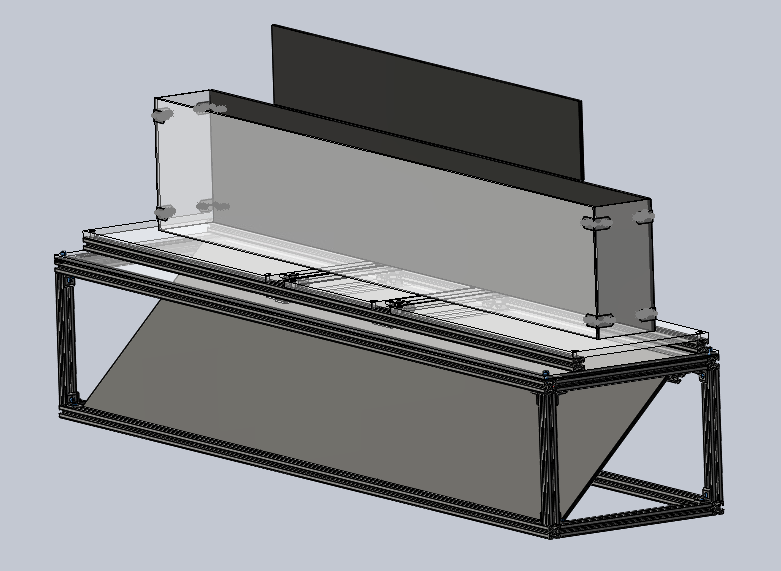
3D model of spatiotemporal and dynamic gait arena
| edgar.sldasm |
Arena Structure, Animal Enclosure, and Optional Lighting Structure
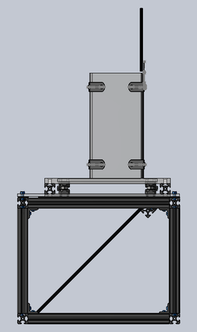
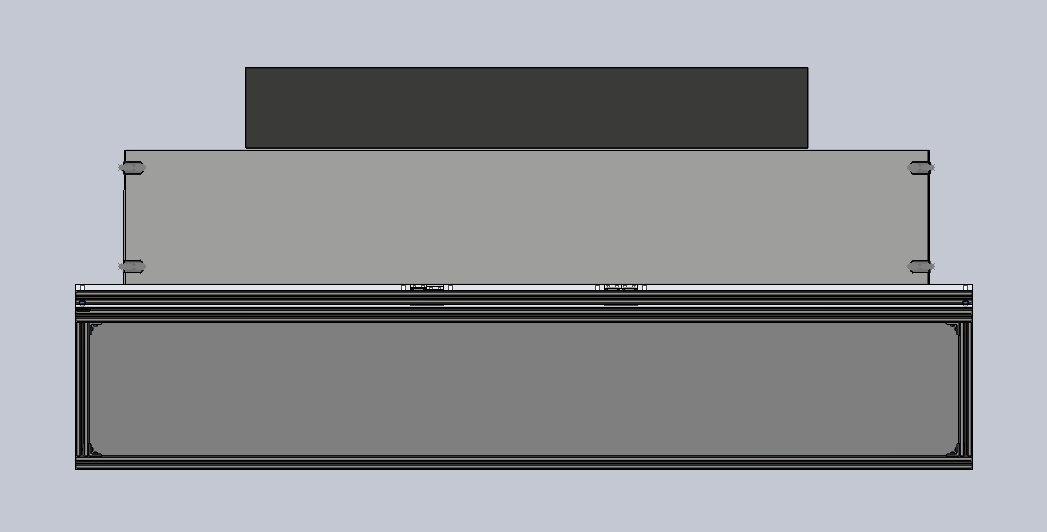
The arena structure, animal enclosure, and optional lighting structure should be constructed as per the recommendation and instructions on the "Spatiotemporal Arena" page. The primary difference between the spatiotemporal only and dynamic collection enabled arena is the secondary, instrumented floor described below. The dimensions provided for the instrumented floor are such that the spatiotemporal arena animal enclosure fits within the width of the instrumented panels. Should you require a wider animal enclosure, please consider the necessary, corresponding changes to the instrumented floor dimensions when beginning construction. The "Critical Components" page provides additional insight on modification of your EDGAR build.
The arena structure, animal enclosure, and optional lighting structure should be constructed as per the recommendation and instructions on the "Spatiotemporal Arena" page. The primary difference between the spatiotemporal only and dynamic collection enabled arena is the secondary, instrumented floor described below. The dimensions provided for the instrumented floor are such that the spatiotemporal arena animal enclosure fits within the width of the instrumented panels. Should you require a wider animal enclosure, please consider the necessary, corresponding changes to the instrumented floor dimensions when beginning construction. The "Critical Components" page provides additional insight on modification of your EDGAR build.
Instrumented Floor
1. Drill holes into the two 23’’ x 12’’ x 0.5’’, the 12’’ x 12’’ x 0.5’’, the two 1.25’’ x 12’’ x 0.125’’, and the two 1.25’’ x 9.5’’ x 0.125’’ acrylic sheets as specified in Drawings 2-5.
2. Create the force platforms by attaching the 1.25’’ x 9.5’’ x 0.125’’ acrylic sheets on top of two force links, and the 1.25’’ x 12’’ x 0.125’’ acrylic sheets to the bottom of the force links using the black oxide stainless steel Phillips flat head screws. Screws must be countersunk.
- Position the force links so the cables face outside
3. Attach the acrylic sheets on top of two 63’’ 80/20 bars in the arrangement seen in the figure below. Screws for the acrylic sheets should all be countersunk. The 1.25’’ x 9.5’’ x 0.125’’ acrylic sheets should not touch the 80/20 bars. The 1.25’’ x 12’’ x 0.125’’ acrylic sheets should be attached to the bottom of the 80/20 bars. Leave a thin space (about 1 mm) between the force platforms and the other acrylic sheets. Line the bottom of the 63’’ 80/20 bars with the foam stripping where there is no force platform. Run the cables of the force plates along the inside of the 63’’ 80/20 so the cables are not seen in-between the force links. You may want to tape the cables down so they do not move.
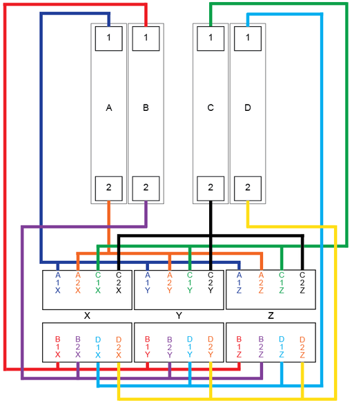
4. The following figure illustrates the manner in which our group has summed our force cubes (connections between our channel gang connectors and summing boxes). It should be noted that this setup is specific to our equipment, and should only be used a suggestion for summing and naming conventions. Additionally, steps 5-7 remain specific to our setup. Force links, cabling, summing boxes, DAQ, and amplifiers have not been included in the materials table. Please contact our group if you are interested in the specific components of our dynamic set up.
- Force Platform Naming Convention:
- There are four force platforms: A, B, C, and D
- Each force platform has two force links: 1 and 2
- Each force link has three cables: X, Y, and Z
- Force platforms A and C are summed by channel
- Force platforms B and D are summed by channel
5. Use a BNC cable to connect each summing boxes to the “input” terminals on the back of the amplifiers. BNC cables from A/C summing boxes should go to the back of the same amplifier. BNC cables from B/D summing boxes should go to the back of the second amplifier.
6. Connect the amplifiers to the DAQ using a BNC cable to the “Output” terminal on the back of the amplifier to the “Analog input” terminals on the DAQ. There should be six total cables connected from the back of the amplifiers to the DAQ (three each for A/C and B/D).
7. If using remotes, connect the remotes to the back of the amplifier in the “Remote Control” terminal. You should have two remotes, one for A/C and one for B/D. We use the remotes to reset the amplifiers while gait testing.
8. Place the instrumented floor on top of the animal enclosure.


